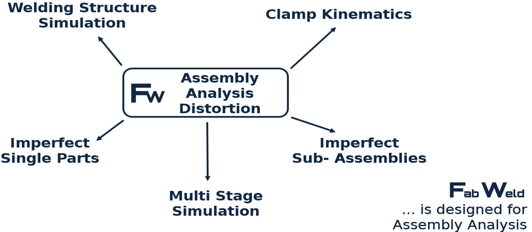
Manufacturing simulation goes beyond pure welding simulation. In manufacturing simulation, the assembly process must be mapped.
This includes the consideration of the clamping kinematics, i.e. the simulation of the clamping process, the consideration of imperfect individual components and the consideration of imperfect subassemblies. Furthermore, a multi-stage simulation must be performed for the assembly, in which additional components are added to the previously calculated subassembly from stage to stage. In addition, upstream or downstream forming operations, cutting operations or heat treatment sections can also become relevant for the manufacturing simulation and must also be represented in the simulation.


Form deviations occur during the production of welded sheet metal assemblies (vehicle bodies and components, exhaust systems, power plant components, household appliances and many others). Both thermal distortion from the welding process, the occurrence of buckling problems, and distortion when clamping imperfect individual components contribute to this. With our software we can calculate this form deviation already in the design stage and suggest compensation measures.
Dr. Loose GmbH deals with thermal joining and manufacturing simulation. Manufacturing simulation helps to optimally design modern high-tech manufacturing processes. On the one hand, this enables companies to save costs in manufacturing, and on the other hand, they are also in a position to be able to realize demanding manufacturing stages at all.
In the past, weld structure simulation for the prediction of deformations and residual stresses was usually only applied to small components. Investigations and validations were carried out on small test examples. In the meantime, a state of the art has been reached for this simulation methodology, with which accurate results with excellent agreement to reality can be achieved. However, small assemblies are of less interest in industrial applications, since welding tests can be performed faster and at lower cost. The situation is different for large structures and multi-stage assemblies. Trial welds are becoming increasingly expensive, especially when large special tools have to be changed without sufficient certainty about the effectiveness of the measure. Here, simulation helps massively to save costs in the development of the production line and the production design.
In car body manufacturing, it is a great challenge to keep the deviation of the manufactured structure from the target geometry (CAD) within desired limits. The manufacturing process should be secured simultaneously and parallel to the product development at a very early stage. Production systems are sometimes designed before the manufacturing process has been validated in terms of feasibility and the tolerances to be achieved. For example, the number of production stations, cycle times and the robots with action specifications are already fixed. If problems with the dimensional accuracy of the end product occur at a late stage of development, the possibilities for countermeasures are limited due to the boundary conditions that have already been set. This can be avoided by using a powerful simulation tool:
The best measure is to use assembly simulation at an early stage:
Dr. Loose has developed a simulation tool with special methods that meet the requirements of accurate assembly simulation. The most important features are:
Up to now, in the simulations, the filler metal is firmly bonded to the components at the start of the calculation, even for seams that have not yet been welded. Although it is possible to reduce the stiffness of these joints, which do not yet exist, by intervening on the material side, this procedure still significantly distorts the results. Dr. Loose has developed a special simulation method in which this error does not occur, but the still unwelded components can move freely. This enables Dr. Loose to detect gap formation during welding. Clamping or tacking concepts can be designed so that no critical gaps occur. Conversely, processes can also be better designed using this metthod, because the locations for tack welds or clamping tools can be determined as a result.
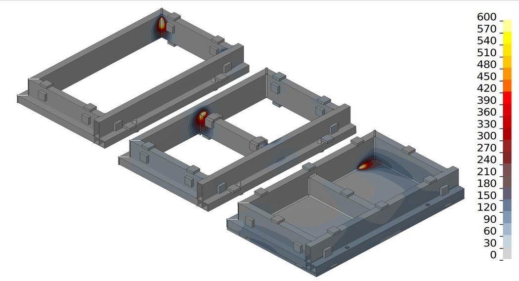
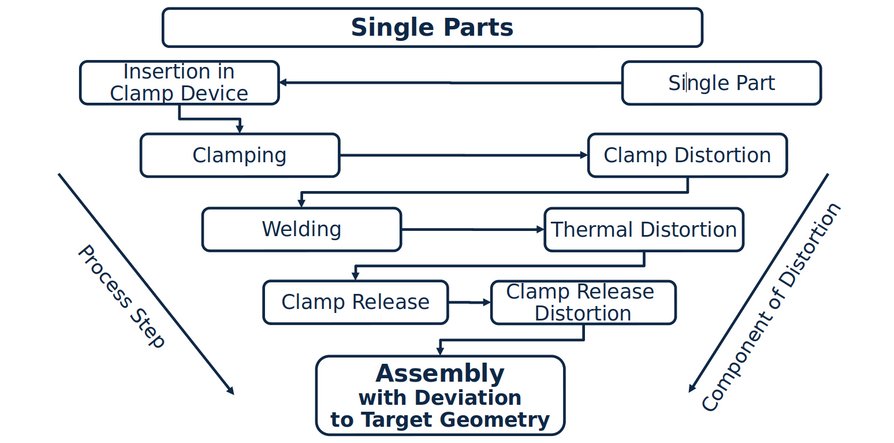
The clamping of the components results in another significant influence on the assembly distortion. Closing the clamps imprints an additional deformation and stress component as soon as the individual components or subassemblies already have geometry deviations from the CAD zero position from previous manufacturing steps. Such clamping distortions are "frozen" by the joining process. In addition, pre-deformations by clamps can be deliberately designed to compensate for distortion. FabWeld takes the clamping process into account in the simulation, including specified clamping paths or clamping forces. The assembly of a car body or welded structure usually takes place in several stations. First, sub-assemblies are manufactured, which are assembled to the main assembly in further steps. This multi-stage process is simulated with FabWeld in a process-true manner. The state variables deformation, stresses, contact and residual temperatures from the first calculation stage are transferred to the next stage as input variables.
With the methods shown, the assembly distortion of large sheet metal structures can be calculated accurately. The assembly calculation can and should be carried out in the early design phase, since it can be used to design the concept for warpage compensation.
Warpage management with FabWeld enables production planning which, in contrast to current practice, requires almost no subsequent tool corrections on the production line.

Process steps during assembly and associated distiortion components
© Dr. Loose GmbH, alle Rechte vorbehalten | Impressum | Datenschutz | Rechtliche Hinweise